Item Code Item Name
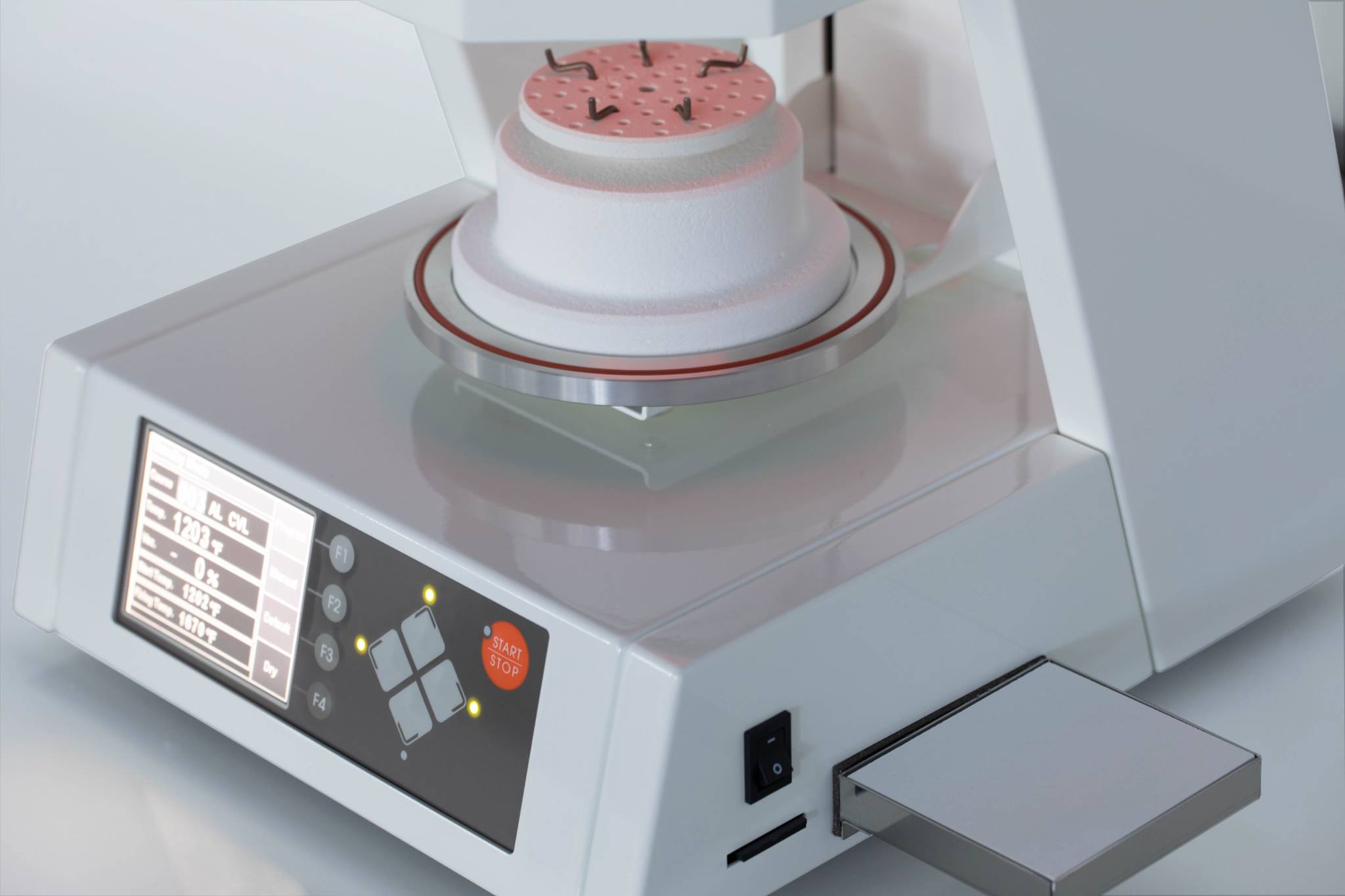
MSP-019501 Firing Stand
MSP-019502 Firing Tray
MSP-019503 Tray Stand Assembly
MSP-019504 Long Firing Peg
MSP-019505 Short Firing Peg
MSP-019506 Ceramic Tray
MSP-019701 Thermocouple
MSP-019703 Muffle Assy (120V)
MSP-019902 Fan Assy (120V)
MSP-020001 Solenoid Valve for Vacuum Assembly
MSP-020002 Solenoid Valve for Release Assy
MSP-020004 Control PCB (120V)
MSP-020008 Solenoid Valve for Pump Release Assy
MSP-02005 Control PCB (220V)
MSP-020101 Operation PCB
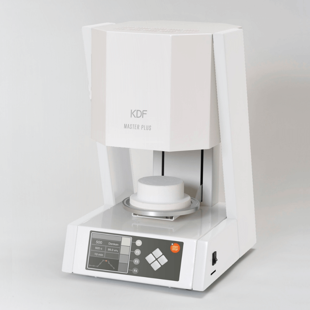
MSP-C000GL Master Plus machine (1212J-GW)
Periodic Machine Cleaning

Firing Table:
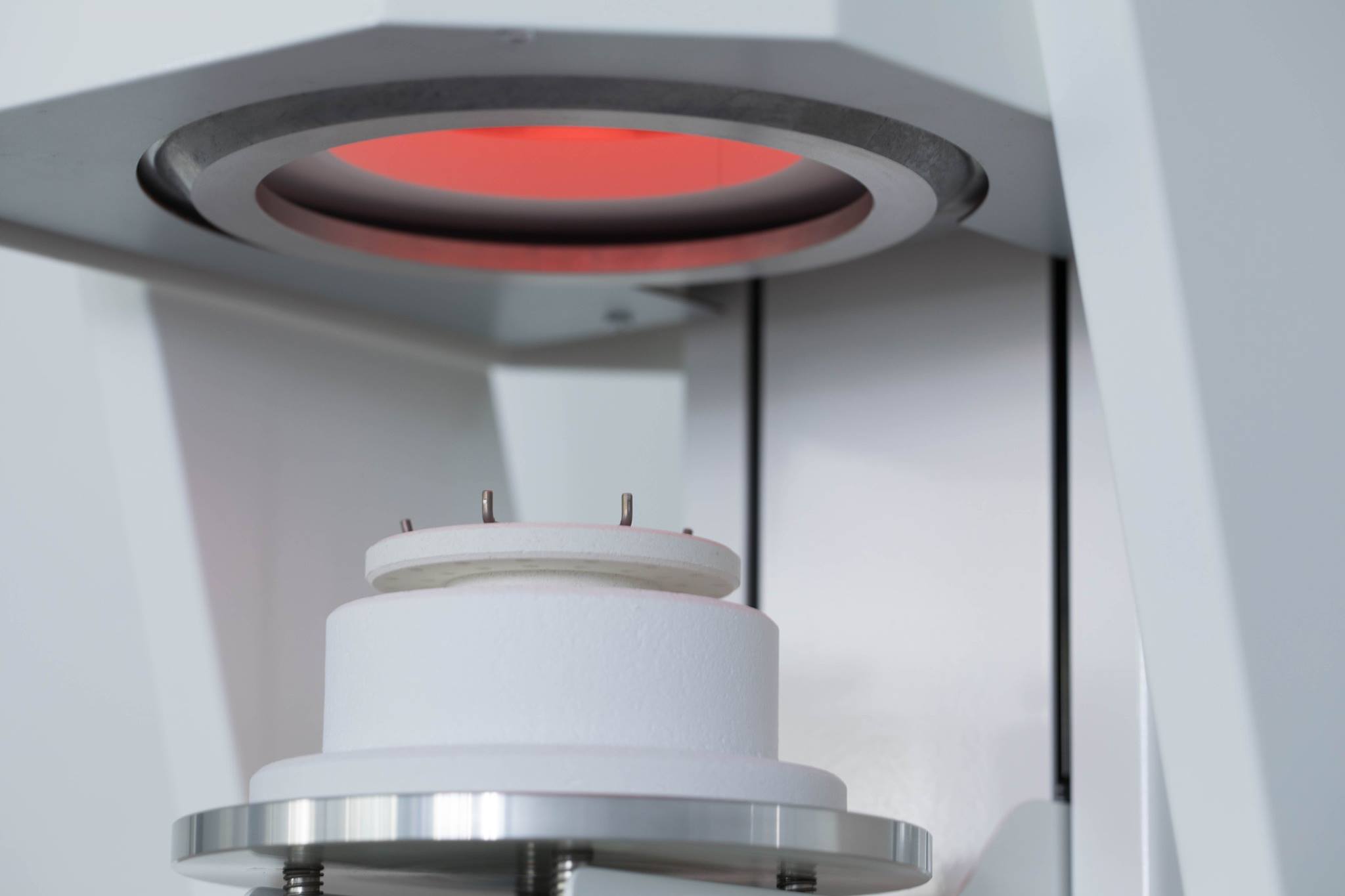
When the muffle and firing stand is cold, remove the firing stand and wipe with alcohol.


Maintenance Part Replacements

Temperature Sensor Replacement:

  1. Remove the 4 screws shown on drawing 1 to remove the leftcover and right cover.
  2. Remove the 4 screws shown on drawing 2 to remove the muffle cover.
  3. Remove the 2 screws shown on drawing 3 to remove the red and white line connected to the temperature sensor.
  4. Remove the 2 nuts shown on drawing 4 to remove the temperature sensor.
  5. Install the new temperature sensor. We will complete installation by following the previous direction in reverse order.
    (Caution) The temperature sensor has polarity. Re-connect the red line to the “+” terminal and re-connect the white line to another terminal.
  6. Once the replacement is complete, re-plug the power cord into the electrical outlet and power on the unit.
  7. Check to see if the temperature rises. If the temperature lowers or display 32 (0℃), the connection line to the temperature sensor is reversed. Please re-check.


Muffle Replacement:
  1. Remove the temperature sensor. See the “Temperature Sensor Replacement” for more information.
  2. Remove the 2 screws shown on drawing 1 to remove the white lines connected to the heater terminal.
  3. Remove the 2 nuts shown on drawing 2 to remove the piping terminal.
    ※The replacement of piping is not required.
  4. Remove the 4 screws shown on drawing 3 to remove the muffle.
  5. Install the new muffle. We will complete installation by following the previous directions in reverse order.
    (Caution) Be sure to plug in the line securely to the end when re-connecting the line back to the heater terminal. If the line is not securely plugged in, it will become hot and dangerous.
  6. Once the replacement is complete, re-plug the power cord into the electric outlet and power on the unit.
  7. Check to see if the temperature rises. If the temperature lowers or display 32 (0℃), it could possibly be that the connection line to the temperature sensor is reversed. Please re-check.
  8. After replacement the new muffle, there may be instances where there is moisture inside the muffle. Before using, please refer and run the “Unloaded muffle firing”.


Error Messages:
  • No2: Microcomputer is abnormal –
    Displayed when the microcomputer operates abnormally due to noise
  • No3: Abnormal air release –
    Displayed when it takes more than 20 seconds from vacuum atmosphere to air release
  • No4: Abnormal movement of firing table –
    Displayed when the abnormal up/down movement of the firing table occurs
  • No5: Abnormal temperature rise –
    Displayed when the temperature does not rise or the temperature sensor is not working properly
  • No6: Abnormal temperature sensor –
    Displayed when the temperature sensor malfunction
  • No7: Abnormal vacuum creating –
    Displayed when the vacuum is not able to pull up to capacity value. Try performing “Vacuum Check” in maintenance mode.
  • No8: Abnormal memory –
    Displayed when the data in the memory has been corrupted and the reading and writing of memory is not working properly due to noise. When the power is turned off/on, it may be fixed but there is a possibility that program data may be erased.
  • No9: Abnormal temperature rise in muffle –
    Displayed when the temperature of the muffle rises abnormally


Instructions

Other Products

Cascom SE
Neo Super Cascom
Zircom
007 PL
Wax Master II


For more information, please contact us.